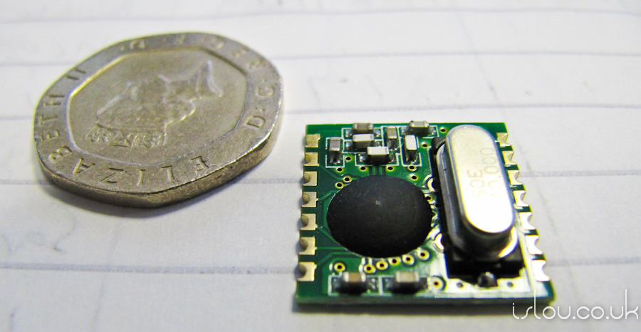
The ALPHA RF Transceiver Module 433MHz

ALPHA RF Transceiver Module 433MHz SMT
Introduction
These were found whilst looking into potential ways of implementing wireless communications. They don’t offer the most straight forward way of communicating between the micro-controllers for the system but have an impressive amount of functionality for their price.
These were purchased from RS at £3.90 per unit. (http://uk.rs-online.com/web/search/searchBrowseAction.html?method=getProduct&R=6666757)
Specs:
Research
+ Physical Unit
Potential Problem: Due to the 2mm pitch it is not possible to solder pins which will fit straight onto a breadboard for prototyping. A PCB the units can be soldered to with standard sizes will have to be created.

Dimensions for ALPHA RF module (From Data sheet)
+ Pinout

Pin-out for ALPHA RF module (From Data Sheet)
Pins of interest:
| PIN | Definition | Function |
| 1 | SDO | Serial Data Out Pin |
| 2 | nIRQ | Interrupts request output?active low? |
| 7,10 | GND | Power ground |
| 8 | ANT | Antenna Connection |
| 9 | VDD | Positive power supply |
| 12 | SDI | SPI data input |
| 13 | SCK | SPI clock input |
| 14 | nSEL | Chip select (active low) |
+ The SPI Interface
It seems everything can be done via the SPI interface. All parameters are set to default on power on and only retained whilst the unit is in sleep mode. This means some kind of initialization routine will be required.
+ SPI Tech Details:
- Data bits on pin SDI are shifted into the device upon the rising edge of the clock
- Data is only shifted in when pin nSEL (slave select) is LOW
- All data are sent MSB first
+ nIRQ Interrupt Request
IRQ generated on the following events (nIRQ pin pulled low):
- The TX register is ready to receive the next byte (RGIT)
- The RX FIFO has received the pre-programmed amount of bits (FFIT)
- Power-on reset (POR)
- RX FIFO overflow (FFOV) / TX register under run (RGUR)
- Wake-up timer timeout (WKUP)
- Negative pulse on the interrupt input pin nINT (EXT)
- Supply voltage below the pre-programmed value is detected (LBD)
Links
http://www.rfsolutions.co.uk/acatalog/FM_Radio_Modules.html
http://www.rfsolutions.co.uk/acatalog/DS-ALPHATX-4.pdf
Data Sheet with more info > http://www.rfsolutions.co.uk/acatalog/DS-ALPHA-TRX-6.pdf
They seem much like these units > http://www.hoperf.com/rf_fsk/rf_transceiver.htm


Leave A Comment